


;)

Carbon Capture and Sequestration: A Global Perspective
Human activities to provide food, energy and Materials result in emission of Greenhouse Gases (GHG’s), one of the prime gases of GHG being Carbon Dioxide (CO 2). Large amounts of CO2 emissions in the atmosphere result in undesirable climate changes. Climate change has become one of the most pressing challenges facing humanity in the 21st century. Climate change and especially Global warming would not only increase high heat related disorders in the population, putting an enormous strain on the already strained Healthcare systems worldwide but also could result in fatalities.
The estimated 2024 Carbon Dioxide emissions from Fuel Industry excluding land use change are about 39-40 GT (Billion tons). USA contributed about 15% of these emissions.
As the world grapples with rising temperatures, extreme weather events, and the long-term impacts of greenhouse gas emissions, innovative solutions are urgently needed. Among these, Carbon Capture and Sequestration (CCS) stands out as a promising technology with the potential to reduce atmospheric carbon dioxide (CO 2) levels. CCS does not come in the way of Industrial progress or Industrialization but helps mitigate the impact of the emissions of Carbon Dioxide resulting from the Industrial Activity by providing a system to capture, process, transport and sequestrate the emitted Carbon Dioxide.
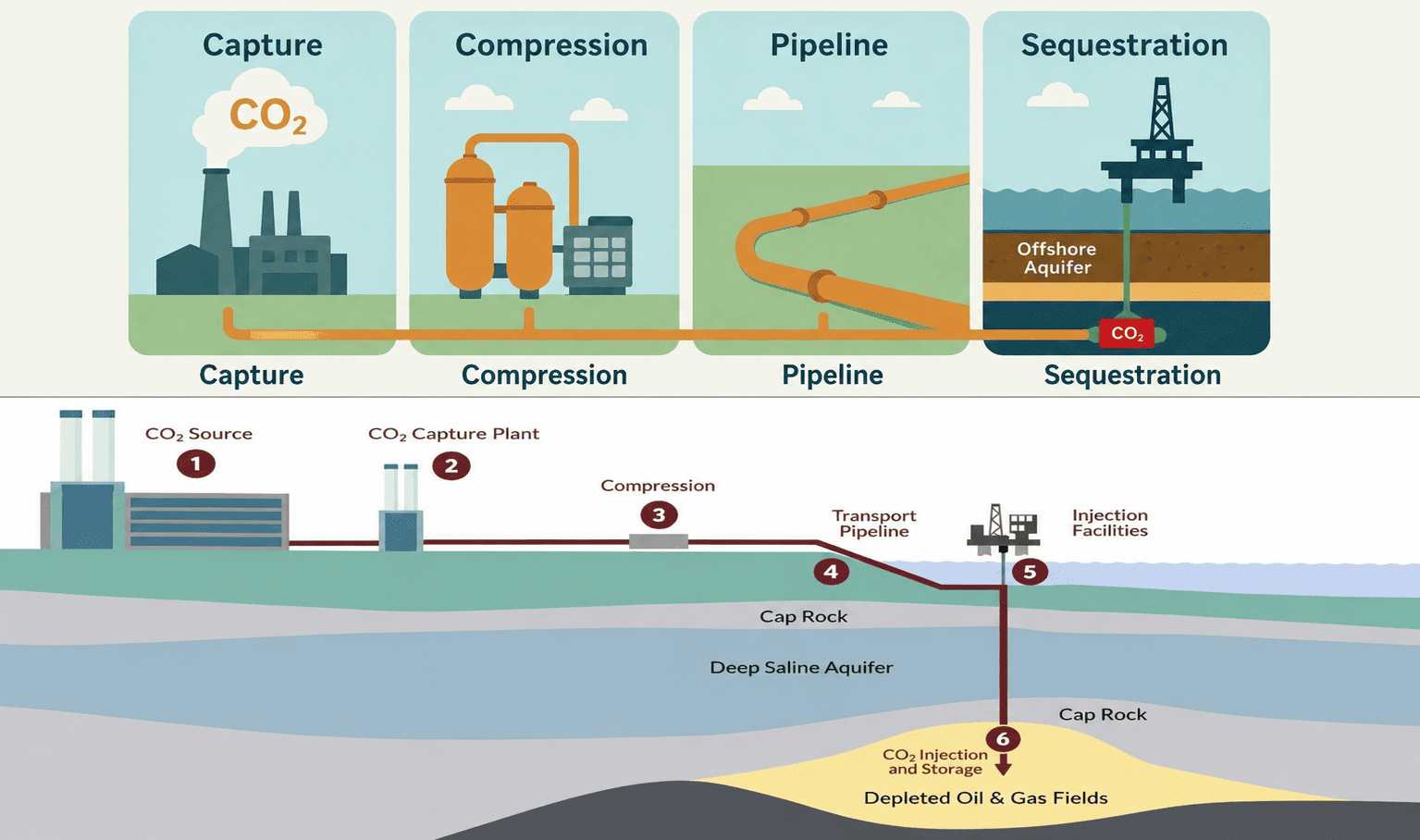
Carbon Capture and Sequestration: Carbon Capture and Sequestration refer to the process of capturing CO2 emissions from sources such as power plants, LNG installations, Process plants like Hydrogen & Ammonia production units, Refineries and other industrial facilities and storing it safely underground, in geological formations. The goal is to prevent CO2 from entering the atmosphere, thereby reducing the impact on climate change. CCS involves four main steps.
- Carbon Dioxide Capture:
Carbon dioxide is captured from the CO2 bearing exhaust gases of an Industrial source.
Carbon Capture Capex and Opex costs increase exponentially as the concentration of CO2 gets lower. Hence, the lowest cost option for a CCS system is to capture the CO2 from streams with higher concentrations.
- The large CO 2 stationary sources emitting CO 2 in the order of decreasing concentrations of CO 2 are(in Vol%):
- LNG Plants where Natural gas is pretreated to remove all the CO2 before Liquefaction which gives a 95% and above pure CO2 stream which can be further polished and compressed and
- The stream after separating Industrial Hydrogen from Gray Hydrogen Steam Methane Reformer plants in Refining, Ammonia, Chemical and Blue Hydrogen plants. The concentration of CO2 is in the range of 45-60 vol%.
CO2 can also be captured from the stream after shift reactor in this plant where the CO2 concentration would be around 20%. However, these two streams yield about 80% of total direct CO2 emissions from the plant. There is a third stream which contains CO2, the flue gas from the Steam Methane Reformer having 15% CO2 concentration and if CO2 is captured from this stream also, then a total of 95% of the CO2 emissions from the Hydrogen Generation unit can be captured.
- Steel Plants : Blast furnace gas after combustion which has about 27% concentration of CO2 or Blast furnace gas before combustion which has about 20% concentration of CO2 .
- Cement plants : Kiln off gases containing about 14 to 30% CO2
- Power Plants:
- IGCC after combustion contains 12-14% concentration of CO2
- Coal fired Boilers – 12-14% concentration of CO2
- Oil fired Boilers – 12-14% concentration of CO2
- Gas fired Boilers – 11-13% concentration of CO2
- Power station Flue Gas – 7-10% concentration of CO2
-Natural Gas Boilers – 3-4% concentration of CO2
1.2) Capture Methodologies/Technologies:
At present, majority of commercially available technologies use proprietary enhanced Amine solutions for absorption of CO2 which is the predominant Carbon Capture process.
Comparison of various Carbon Capture Technologies:
Care should be taken while selecting the Capture technology for emissions from different sources which contain widely varying concentrations of CO2 . Various techno economic studies based on the actual composition of emissions from a specific site is carried out during “Feed Engineering” and a technically suitable and cost-effective technology is chosen before proceeding with the “Detailed Engineering “phase.
Carbon Capture and Sequestration Continues…
- Compression:
After carbon Capture, the next step is compressing the pure CO2 stream to the required phase and pipeline pressure for long distance transportation to the Sequestration site.
But, prior to compression, the moisture content and Hydrogen sulfide content in the gas need to be reduced to CO2 pipeline specifications. Especially moisture content in the gas stream would give rise to carbonic acid which is very corrosive to carbon steel pipeline. Various CO2 pipeline operators in USA specify slightly differing levels of moisture. The most common specification for allowable moisture content in CO2 pipelines is in the range of 630 ppm to 250 ppm. Hence, necessarily, a dehydration pretreatment step is required upstream of the compressor or pump.
It is also proven that the most techno economical state of transporting CO2 through a pipeline is for CO2 to be in dense phase liquid (super critical liquid). The dense phase of CO2 enables flow through a much lower diameter pipe for the same flow rate when compared with the Gas phase transport and hence results in the overall lower cost of the CCS system. Compression stations are required typically every 100 miles (approx. 150 kms) onshore.
The phase diagram of CO2 shows the range of operating conditions for CO2 transport through pipelines.
- Pipeline transport: Moving the captured CO2 via pipeline to the offshore Saline aquifer sequestration site or to an onshore sequestration site is the next step in the With the moisture content in the range of 630-250 ppm, carbon steel pipe can be selected from corrosion aspect. However, at 630 ppm moisture content level, the designer should check against the possibility of Hydrate formation if there are likely to be cycles of depressurization and pressurization during the operation. To avoid this, it is better to aim to reduce the moisture content to the lower limit of 250 ppm.
Sequestration: In the USA, larger sequestration pore spaces are found in Saline aquifers offshore though few onshore sequestration sites could be
The pure dried and compressed CO2 is injected deep into the selected aquifers. Though CO2 in dense phase with 250 ppm moisture content can be transported in Carbon steel pipeline without getting subjected to corrosion, the downstream injection well head would need anti corrosive materials to handle the CO2 at this moisture level. So, it is a cost benefit analysis that is to be made between choosing the costly SS internals for the wellhead vs bringing down the moisture content in the dense phase CO2 to 50 ppm at the dehydration stage. At this level of moisture, Carbon Steel internals at the injection wellhead can handle the CO2 without getting subjected to corrosion.
For selecting suitable aquifers, lot of 3 D seismic studies and CO2 plume analysis of injected CO2 need to be done before an operator could file for getting the permit to drill a Class VI well. In the USA, CO2 injection wells are permitted only in Class VI type of wells.
EPA has stringent stipulations for getting the permit to drill a Class VI well. Also, EPA stipulates a very comprehensive, stringent and ongoing analysis and reporting regimen after the CO2 is injected into a Saline Aquifer often at depths of about a mile below the Ocean ground and below a leakproof Caprock layer. Hence, there can be no apprehension that Sequestrated CO2 plume could leak into either drinking water aquifers or could harm marine life or human health. These EPA requirements can be obtained by the designers, operators, etc. before they prepare the application for a permit to drill a class VI type well for sequestration of CO2. These requirements are either enforced directly by EPA or in some instances EPA utilizes an authorized state agency to act on their behalf in enforcing these requirements.
For example, in the state of Texas, the Railroad Commission of Texas (RRC) is the sole overseeing agency to handle all aspects of Class VI permitting, including reviewing Geological data, modelling Plume movement and ensuring protection of underground drinking water. Five more states, North Dakota, Wyoming, Louisiana, West Virginia and Arizona were allowed by EPA to handle all permitting matters pertaining to Class VI wells. It takes anywhere from 1.5 to 2 years to obtain EPA Class VI Well permit after submission to the designated authorities.
Carbon Capture and Sequestration in the United States
The United States is a global leader in CCS technology and deployment. The US has more than a decade of experience in carbon capture, particularly in the oil and gas sector. As of 2025, the US has over 15 commercial CCS facilities in operation, with a combined annual capture capacity of approximately 25 million metric tons of CO2. The Petra Nova project in Texas, for example, was one of the largest post-combustion carbon capture projects, capable of capturing 1.6 million metric tons of CO2 per year.
The US Department of Energy has invested billions of dollars in CCS research and demonstration projects. According to the Global CCS Institute, there are over 30 CCS projects in various stages of development in the US, which could increase the country’s annual capture capacity to over 70 million metric tons by 2030.
- In 2022, US CCS projects captured about 20 million metric tons of CO2, equivalent to removing roughly 4 million cars from the road.
- The US has over 5,000 miles of CO2 pipelines, the most extensive network in the
- In 2023, the US government announced $2.3 billion in funding for new CCS demonstration projects.
Carbon Capture and Sequestration in Canada
Canada has made significant strides in CCS, particularly in the province of Alberta, where oil sands production is a major source of emissions. The country’s flagship CCS project is the Quest facility, operated by Shell, which has captured and stored more than 7 million metric tons of CO2 since starting operations in 2015. Canada also hosts the Boundary Dam project in Saskatchewan, the world’s first commercial-scale CCS project on a coal-fired power plant.
Carbon Capture and Sequestration Continues…
- Canada’s total annual CCS capacity is about 4 million metric tons of CO2 as of
- The Quest project alone captures approximately 1 million metric tons of CO2 per year.
- Canada aims to capture and store 15 million metric tons of CO2 annually by 2030 as part of its climate action plan.
The Canadian government has committed substantial funding to CCS, including a $319 million investment announced in 2021 to support new projects and research. The Pathways Alliance, a coalition of major oil sands companies, has proposed a $16.5 billion CCS network to capture up to 10 million metric tons of CO2 per year by 2030.
Carbon Capture and Sequestration in Europe
Europe has positioned itself as a pioneer in climate action, with CCS playing a crucial role in its net-zero strategies. The European Union’s Green Deal and Fit for 55 package emphasizes the deployment of CCS, especially for industrial decarbonization. Norway’s Sleipner and Snøhvit projects have been operational for over two decades, collectively capturing more than 25 million metric tons of CO2 to date.
- As of 2025, Europe has 10 large-scale CCS facilities in operation, with a total annual capacity of about 10 million metric tons of
- The Northern Lights project in Norway, expected to start operations in 2026, will transport and store up to 1.5 million metric tons of CO2 annually, with plans to expand to 5 million metric tons.
- The UK government has committed £1 billion to support CCS clusters, aiming to capture 20-30 million metric tons per year by 2030.
The Netherlands, UK, and Denmark are also investing in CCS infrastructure, including CO2 transport networks and offshore storage sites in the North Sea. The European Commission estimates that CCS could account for the removal of 300 million metric tons of CO2 annually by 2050 across the continent.
Carbon Capture and Sequestration in Asia
Asia, home to some of the world’s largest emitters, is beginning to embrace CCS as part of its decarbonization efforts.
China, Japan, South Korea, and India have launched pilot projects and established national CCS strategies. China currently leads Asia in CCS deployment, with over 40 pilot and demonstration projects.
- China’s total CCS capacity is about 3 million metric tons of CO2 per year as of 2025, with plans to scale up to 50 million metric tons by 2030.
- Japan’s Tomokomai CCS demonstration project has stored over 300,000 metric tons of CO2 since 2016.
- South Korea’s Ulsan CCS project aims to capture 1 million metric tons of CO2 annually by 2027.
India is in the early stages of CCS research, focusing on industrial clusters and enhanced oil recovery. The Asian Development Bank (ADB) has supported regional CCS initiatives, and collaboration between countries is growing. Despite rapid industrialization, Asia’s CCS capacity is expected to increase significantly, with China and Japan leading the way.
Median Estimated Costs by Region for CCS (Capture, Compression & transportation and Sequestration): The following chart depicts the median costs for CCS (including Capture, Compression & transportation and Sequestration) by region is depicted below:
Challenges and Barriers to CCS Deployment
Despite its promise, CCS faces several challenges:
High Costs: CCS is capital-intensive, with initial investments ranging from hundreds of millions to billions of dollars.
Public Acceptance: Concerns about safety, environmental risks, and long-term liability persist.
Regulatory Frameworks: Clear policies and incentives are needed to drive investment and ensure safe storage.
Infrastructure: Building pipelines and storage facilities requires significant planning and coordination.
Overcoming these barriers will require continued government support, industry collaboration, and international cooperation.
Future Outlook: Scaling Up CCS Globally
To meet the Paris Agreement targets, the world must dramatically increase CCS deployment. The IEA projects that by 2050, CCS will need to account for about 15% of cumulative emissions reductions.
This means scaling up from the current global capture capacity of around 40 million metric tons per year to several billion metric tons.
Global CCS capacity in 2025: ~40 million metric tons CO2 annually
Required by 2050: ~7.6 GT or billion metric tons CO2 annually
Collaboration between governments, industry, and research institutions is key. International frameworks, such as the Mission Innovation Carbon Capture Challenge, are fostering knowledge-sharing and accelerating progress.
Carbon pricing, subsidies, and investment in research will also play critical roles.
Future Research Directions in CCS
There are several promising avenues for future research in Carbon Capture and Sequestration. One area is the development of next-generation capture materials that are more selective, durable, and energy-efficient, which could significantly lower operational costs. Besides improved solvents, Metal Oxide Frameworks (MFO’s) are a promising route for Carbon Capture especially for streams with higher concentrations of CO2. Research in this area of CCS is very promising. Another key topic is improving monitoring and verification methods for underground CO2 storage, using advanced sensors and remote sensing technologies to ensure long-term containment and safety. Additionally, integrating CCS with hydrogen production and expanding its role in decarbonizing hard-to-abate sectors, such as cement and steel manufacturing, are critical topics for future exploration.
Collaborations across regions and disciplines will be essential to drive innovation and address the technical challenges that remain.
Conclusion
Carbon Capture and Sequestration is an essential tool in the fight against climate change. Across the United States, Canada, Europe, and Asia, significant progress is being made, with billions of dollars invested and millions of metric tons of CO2 captured and stored each year. While challenges remain, technological innovation, supportive policies, and global cooperation offer a pathway to scaling up CCS and achieving net-zero emissions. As the world moves toward a more sustainable future, CCS will be indispensable in bridging the gap between current emissions and climate goals.
For policymakers, industry leaders, and citizens, understanding the potential and limitations of CCS is critical. With continued investment and collaboration, CCS can help ensure a livable planet for generations to come.